Outcome:
The present invention relates to a magic cube, and more particularly to a magic cube structure, in which if the user unexpectedly rotates the central block a little degree, the negative torque would rotate the central block back to the original position, so that a recovery of the magic cube structure is smooth.
The present invention relates to a magic cube, and more particularly to a magic cube structure, in which if the user unexpectedly rotates the central block a little degree, the negative torque would rotate the central block back to the original position, so that a recovery of the magic cube structure is smooth.
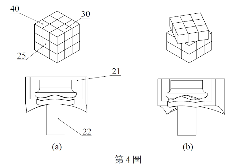
Center pieces movement during a rotation:
|
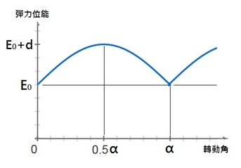
Elastic energy and torque changes during a rotation:
|
|
For one conventional magic cube structure, a central core usually has an elastomer so that when the unexpected rotation degree is just a little, the next step rotation would correct it. Clearly, when the directions of one rotation and the next rotation are the same, the next rotation would correct the unexpected rotation occurring there before. For example, one side of the conventional magic cube structure is rotated ten degrees clockwise, and then the adjacent one is rotated ninety degrees clockwise; as a result, the ten degrees would be corrected. For another conventional magic cube structure, a control block has an inclined face, so that when the unexpected rotation degree is just a little, the next step rotation would correct it. Clearly, when the directions of one rotation and the next rotation are opposite to each other, the next rotation would correct the unexpected rotation occurring there before. For example, one side of the conventional magic cube structure is rotated ten degrees clockwise, and then the adjacent one is rotated ninety degrees counterclockwise; as a result, the ten degrees would be corrected. |
|
Although the conventional magic cube structures could overcome the unexpected rotation, the operation rotation would not be smooth. Therefore, the user would rotate unsmoothly and slowly.
In theory, the resistance to the operation rotation would be a constant value no matter what position the central block is, so that there should not be a tendency to unexpectedly move the central block. However, there would be lots of tolerance during manufacturing, so that the resistance to the operation rotation would not be a constant value at some certain positions and the central block would be unexpectedly moved. The present invention is, therefore, arisen to obviate or at least mitigate the above mentioned disadvantages. |
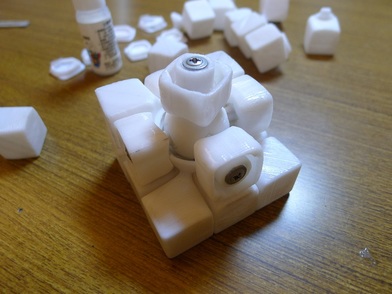
FDM 3D printed prototype:
Link of related patent(U.S.):

|
